Deploying ECMP with NSX for a Provider Logical Router
 Equal Cost Multipathing (ECMP), for the vSphere admin, is ability to create routes with an equal cost, which allows multiple paths to the same network to be created and traffic can be distributed over those paths. This is good for a couple of reasons - firstly is availability. If we were to lose a host, and an NSX Edge, the route will time out quicker than NSX Edge High Availability - thus providing higher availability for our network traffic. Then second reason is throughput - each NSX Edge is capable of ~10Gbps throughput, but with ECMP we can have multiple NSX Edges (up to 8) providing 10Gbps each - that’s a significant performance boost.
Below I’ve mapped out what I want to build in my lab - it’s a simplification of a design I’ve used for some Service Provider customers (and you’ll see similar in the vCloud Architecture Toolkit documentation from VMware).
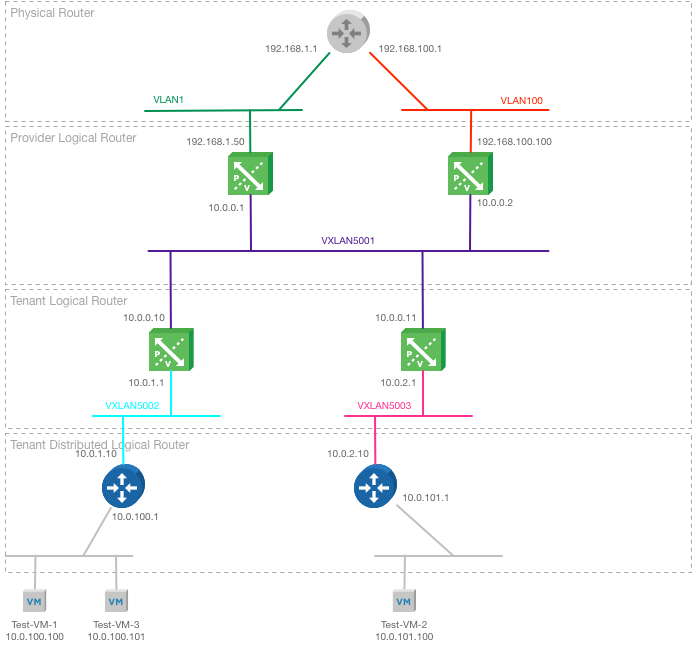
The physical router is my lab EdgeRouter-X and has two VLANs (1 and 100) connected. It’s configured for OSPF Area 0 (backbone) with an interface in both subnets VLANs.
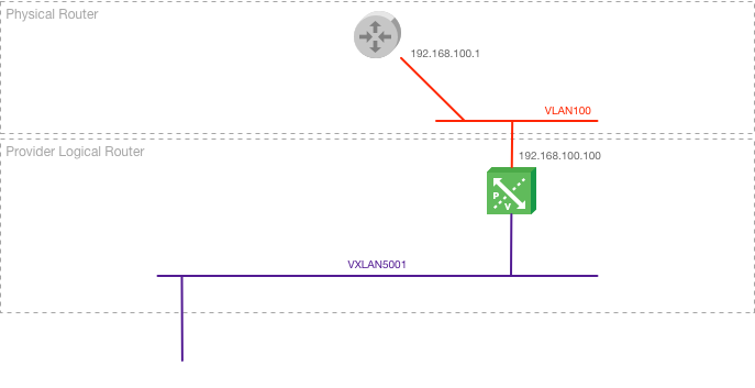
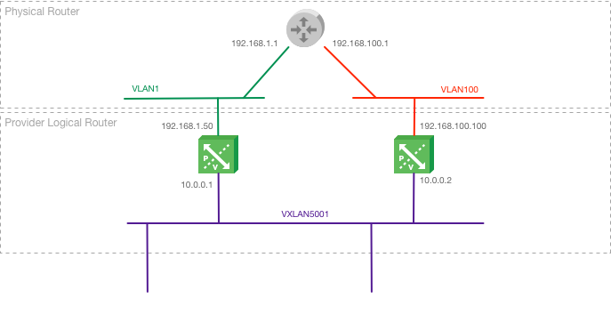
The Provider Logical Router (PLR) provides the North/South traffic to my NSX deployment - anything coming in to or out of the NSX networks goes through the PLR. As I want to provide multiple routes in and out for scalability and resilience, I’ve got two NSX Edges deployed. For ECMP you need to configure a different VLAN for each PLR to connect to the upstream router, so one has an uplink interface to VLAN1, the other to VLAN100. Both have an internal interface to VXLAN5001, which is a Logical Switch supporting my Provider Transit Network.
The Tenant Logical Router (TLR) is the boundary of my tenant’s networks. This is deployed as an NSX Edge with an uplink interface in the Provider Transit Network and an internal interface to my Tenant Transit Network. Each tenant has a TLR, and a Transit Network that is not shared by any other tenants.
Finally, there’s a Tenant Distributed Logical Router (TDLR), which has an uplink interface on the Tenant Transit Network, and as many Tenant Networks (Logical Switches) as are supported - that’s slightly less than 1000 networks. The TDLR is required for scalability purposes, as the TLR is an NSX Edge and limited to 10 vNICs.
OSPF Configuration
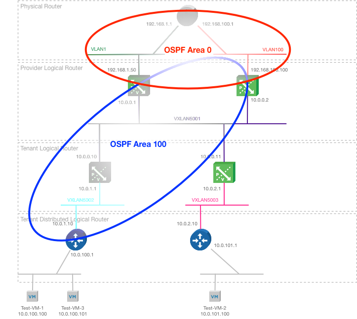
Both the Physical Router and the Provider Logical Router NSX Edges are configured to be in OSPF Area 0. This is my network backbone area, to which all other Areas must be connected. Area 100 encompasses the Provider Logical Router (which become the Area Border Router in OSPF), the Tenant Logical Router and the Tenant’s Distributed Logical Router. The Provider Logical Router is configured with it’s Uplink interface in Area 0 and it’s Internal interface in Area 100.
Deploying the solution
I have pre-deployed the Logical Switches required for this testing:

Physical router
Obviously the physical router configuration is going to be different depending on what physical upstream router you’re using. In my lab I have the very capable Ubiquiti EdgeRouter X, so I configured this with interfaces in my two VLANs (1 and 100) and configured OSPF Area 0. As per the diagram above, the ERX has two addresses, 192.168.1.1 and 192.168.100.1.

At this point, there are no OSPF routes configured, so the EdgeRouter only knows about some connected, and some static routes.
Configuring the Provider Logical Router
The first NSX Edge (PLR-1) is deployed with an uplink in VLAN 100 and internal on the Provider Transport network.
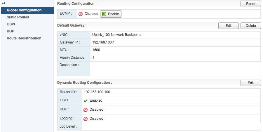
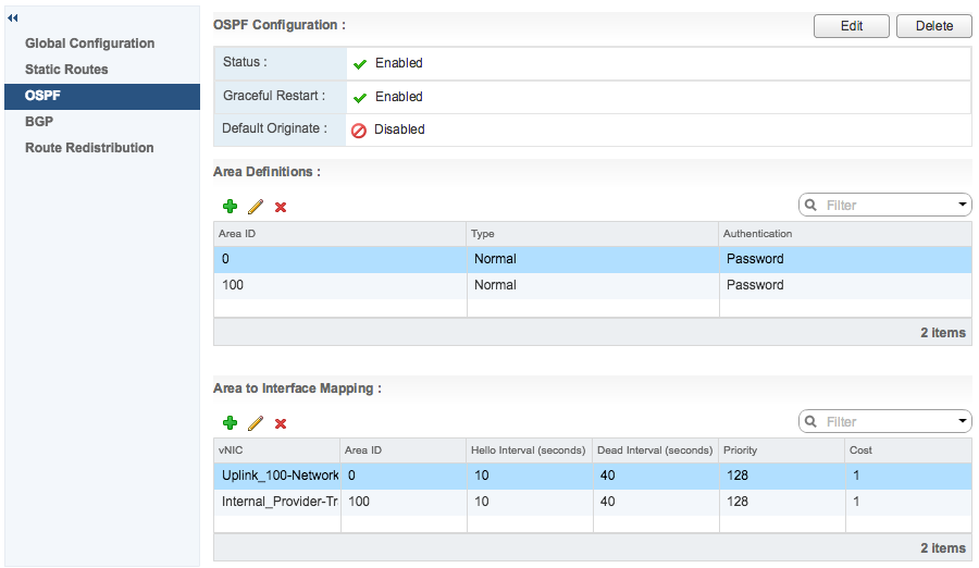
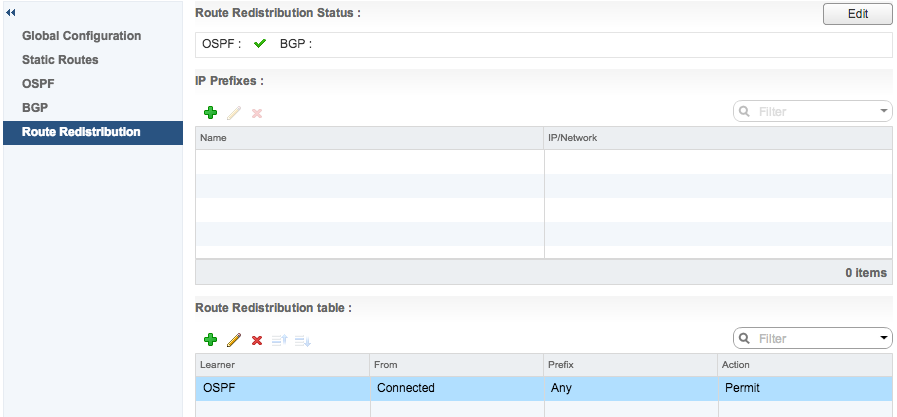
Under Global Configuration you can see that the default gateway is the physical router interface on VLAN 100, and that OSPF is enabled. In the OSPF settings, Area 0 is configured, and an Area to Interface Mapping links Area 0 to the Uplink. Area 100 is configured and mapped to the Internal interface. Under Route Redistribution, you can see that any Connected network (as well as OSPF learned networks) will be redistributed.
Now if we look at the OSPF routes on the physical router, we can see that the subnet for the Provider Transit network (10.0.0.0/24) has been learned, and has a next hop to TLR-1 on 192.168.100.100.

On the PLR-1 console, you can view the OSPF neighbours and route table to verify that the physical router is a connected neighbour:

At this point, I’ve deployed just the one PLR NSX Edge, and both the Physical Router and the Provider Logical Router know about the connected networks.
Configuring the second PLR NSX Edge
The second NSX Edge in the PLR (PLR-2) is deployed in the same way as the first, except this time it uses the second VLAN to talk to the upstream router. When it’s configured you can the output of the physical router’s “show ip ospf neighbour” and “show ip route” commands.

The Physical Router now has two equal cost routes to the Provider Transit Network through the Provider Logical Network
You can also see that both PLR NSX Edges have formed a relationship with the router, and the router now has two routes to 10.0.0.0/24 (Provider Transit network) that have an equal cost, one going over VLAN1 (via 192.168.1.50) and the other over VLAN100 (via 192.168.100.100).
So, now on my diagram you can see that I have deployed the second PLR, and that they are all aware of the connected networks.
Adding a Tenant Logical Router
The Tenant Logical Router NSX Edge (TLR-1) is deployed and an uplink connected to the Provider Transport network, and an internal interface to the Tenant Transport network. OSPF Area 100 is configured and mapped to both interfaces. No default gateway is configured.
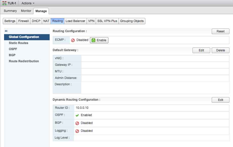
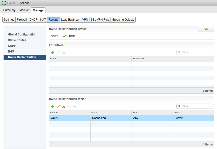
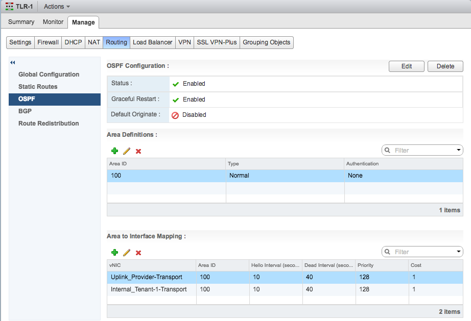
With this configured the physical router learns the following routes:

Physical Router has equal cost routes down through the Provider Logical Router to the Tenant Logical Router
Notice that the route to 10.0.1.0/24 and 10.0.0.0/24 is via 192.168.1.50 and 192.168.100.100 with an equal cost. However, at present, ECMP is not enabled on TLR-1 - so the learned routes will go via 10.0.0.1 (PLR-1) or 10.0.0.2 (PLR-2) but not via both.

The Tenant Logical Router has learned the routes from OSPF but will only show one route per network.
If I enable ECMP on TLR-1 the routes are now available via both 10.0.0.1 (PLR-1) and 10.0.0.2 (PLR-2)
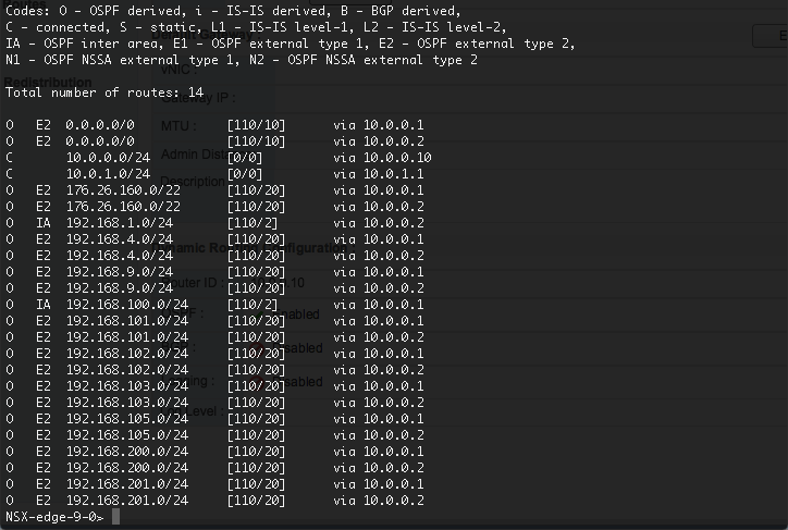
With the ECMP routes enabled on the physical router and the TLR, traffic can now flow in both directions through the Provider Logical Router NSX Edges.
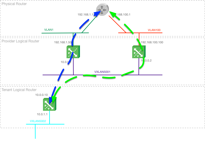
The remainder of my lab build is simple, I deploy a Distributed Logical Router for the tenant, which is configured with it’s uplink in Area 100. It also has an interface connected to a Tenant Network, which is a VXLAN I’ve deployed my VM (Test-VM-1) on.
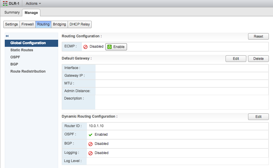
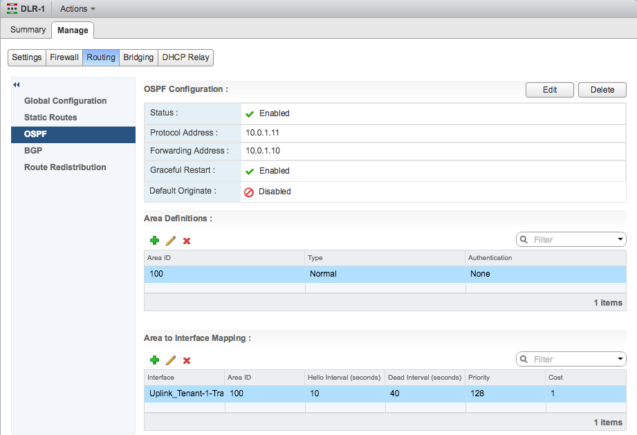
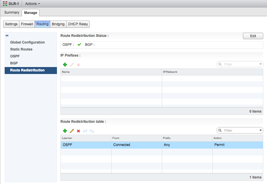
The connected network is replicated via Area 100 to the Tenant Logical Router and Provider Logical Router. The Provider Logical Router replicates the route to the Physical Router via Area 0.

